Device Records Guide
The Device Records User Guide will instruct you on how to integrate time collection devices with eTime Xpress.
Processing Device Time Records in eTime Xpress
(For versions 7.008.000 and above)
Table of Contents
1. Overview
2. eTime Xpress Setup for Processing Device Time Records
2.1. Register Device Units
2.1.1. HandPunch Device Setup
2.1.2. XPocket Device Setup
2.1.3. CSV Setup
2.1.4. TraxG Setup
2.2. Setup Data Format
2.3. Setup Build Shift Rule
2.3.1. Create Build Shift Rule Name and Description
2.3.2. Setup Build Shift Rule for Employees
2.3.2.1. Branch Default Values
2.3.2.2. Mapping Device Employee IDs
2.3.2.3. Shift Matching Rules
2.3.2.4. Rounding Rules
2.3.3. Setup Build Shift Rule for Customers/Sites (Optional)
2.3.4. Setup Build Shift Rule for Services (Optional)
3. How to Process Device Time Records
3.1.1. Import Time Records
3.1.2. Viewing Imported Time Records
3.1.3. Setting Imported Time Records to Ignore
3.2. Post Time Records to Shifts
3.2.1. Build Shifts – Pairing Time Records and Matching to Shifts
3.2.2. Reviewing Build Shift Results
3.2.3. Updating Shifts Before Posting
3.2.4. Reallocating Time Records to Different Shifts
3.2.5. Setting Time Records to Ignore
3.2.6. Setting Process Action
3.2.7. Posting a Shift
3.2.8. Unposting a Shift
4. Device Configuration and Management
4.1. HandPunch
4.1.1. Connecting Power Supply
4.1.2. Connecting Ethernet or Modem
4.1.3. Reset Setup to Factory Defaults
4.1.4. Understanding How to Program HandPunch Units
4.1.5. Setup HandPunch Site Parameters
4.1.6. Recording Hand Prints
4.1.7. Recording Time Records with HandPunch Units
4.1.8. Register HandPunch dll
4.1.9. HandPunch User Manual References
4.1.10. Manage Biometric Templates
4.1.10.1. Import Hand Prints
4.1.10.2. Export Hand Prints
4.1.11. Entering Shift Details (Optional)
4.2. TraxG/EtherTrax/FingerTrax
4.2.1. TraxG Terminal Setup and Enrollment
4.2.2. Enrolling Users
4.2.3. Clocking In/Out
4.2.4. Register Trax dll
4.2.5. Remote Terminal Management via PC Using TraxPort
4.2.5.1. Connecting to Terminal
4.2.5.2. Common SendMessage Commands
4.2.5.3. Loading Firmware and Procedure Files
4.2.5.4. Synchronizing User Codes and Finger Print Templates
4.2.5.5. Turning Off Finger Validation
4.2.5.6. Offline Import of Time Records to eTime Xpress
4.2.5.7. Configuring WiFi on EtherTrax Devices
4.3. XPocket Reader
4.3.1. XPocket Setup
4.3.1.1. Install XPocket Software
4.3.1.2. Connecting to XPocket via XPocket Software
4.3.1.3. Setting Date and Time
4.3.1.4. Updating Device Password
4.3.2. Using XPocket
4.3.2.1. Turning the Reader On
4.3.2.2. Toggling Between Manufacturer and Celayix Program Interface
4.3.2.3. Turning the Reader Off
4.3.2.4. Recording a Clock Transaction (In/Out/Back)
4.3.2.5. Celayix Time Collection Functions Menu
4.3.2.6. Manufacturer Information Menu
4.3.2.7. Creating Time Record File for Import to eTime Xpress
4.3.2.8. Erasing Time Records From Memory
4.3.3. Resetting Device
4.3.3.1. Load Firmware
4.3.3.2. Load Strings List
4.3.3.3. Load Production Program
4.3.3.4. Load Production Table
4.3.3.5. Load Configuration Parameters
1. Overview
This user guide will discuss how to setup eTime Xpress to load and match time records captured from external time collection devices such as HandPunch, TraxG (FingerTrax/EtherTrax) and XPocket. Time records from other 3rd party time collection devices may also be supported using our standard CSV import template.
2. eTime Xpress Setup for Processing Device Time Records
eTime Xpress must be properly configured before it can import attendance information.
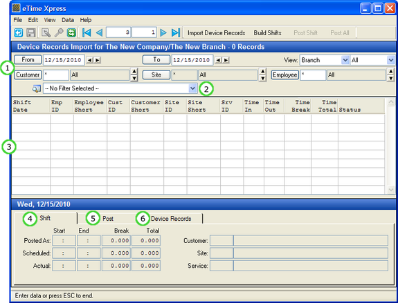
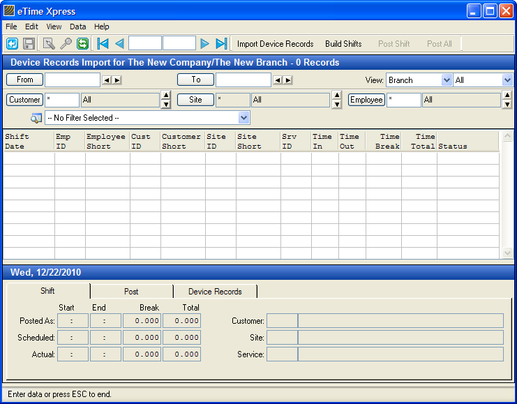
From the Main Menu of eTime Xpress, click Time & Attendance > File > Import > Device Records. The Device Records Import screen should appear as shown in the figure below.
Device Records Import with Annotations
Annotation | Description |
(1) View Selector | Specify the date range and records you want to view. |
(2) Time Record Filter | Select or create a user definable time record filter to search for specific groups of time records. To create your own filters, click button (see the Global Features User Guide for more information). |
(3) Shift Records | Displays time records matched to shifts if available. |
(4) Shift Tab | Displays shift information including posted, scheduled and actual times. |
(5) Post Tab | Displays posted shift information and allows updating of posted information. |
(6) Device Records Tab | Displays attendance information associated with shifts. |
2.1. Register Device Units
Note: Time collection devices should be properly configured and setup before being registered in eTime Xpress. Please refer to the manufacturer's user guide and the setup check list applicable to your device as outlined in the Device Configuration section of this user guide. |
Before time records can be imported into eTime Xpress, the device type and connection setup must be registered.
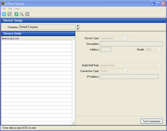
From the Device Records Import screen, click File > Device Setup. The Device Setup screen should appear as shown in the figure below. Register the appropriate devices applicable associated with a Company/Branch.
Device Setup
The setup requirements will vary depending on the type of device. Review the setup descriptions applicable to your devices.
2.1.1. HandPunch Device Setup
If your device is a HandPunch, perform the following setup:
HandPunch Setup | Description |
Device Type | Select HandPunch. |
Description | Specify internal name for device unit (i.e. Main Door etc.). |
Address | Match to 'Set Address' parameter value of the HandPunch. By default, the 'Set Address' parameter value for HandPunches is '0'. |
Model | Specify HandPunch model number. |
Build Shift Rule | Select the build shift rule to be applied when processing time records from this device. Build shift rules are user definable. |
Connection Type | Select how eTime will be communicating with the device and review the applicable connection setup below. |
Connection Type = Direct |
|
IP Address | Specify the internal IP address assigned to the HandPunch. |
Connection Type = Application Server |
|
IP Address | Specify the internal IP address assigned to the HandPunch. |
Connection String | Specify the data source and how to connect to it. Please contact your network administrator for this information. |
User and Password | Specify the user name and password to be sent when connecting to an application server requiring authentication. |
Connection Type = Dialup |
|
Phone Number | If connecting via modem, specify telephone number. |
Baud Rate | If connecting via modem, specify the baud rate. By default, select 9600. |
Click the Test button to validate a direct or Application connection, if applicable.
Important: Microsoft Windows security requires that the user of the PC have local administrator rights in order to establish a remote connection with a HandPunch unit.
If an "Invalid Channel" message is displayed, the connection attempt has failed. Please check that the following items:
- IP Address or phone number is correct; and
- Windows user account has local administrator rights;
- A firewall is not blocking network access to the IP address or port TCP 3001.
2.1.2. XPocket Device Setup
If your device is an XPocket, perform the following setup:
XPocket Setup | Description |
Device Type | Select XPocket. |
Description | Specify internal name for device unit (i.e. Main Door etc.). |
Build Shift Rule | Select the build shift rule to be applied when processing time records from this device. Build shift rules are user definable. |
Connection Type | Select how eTime will be communicating with the device and review the applicable connection setup below. |
Connection Type = Direct |
|
Filename | Specify the path and filename where the XPocket time record file should be imported from. |
Connection Type = Application Server |
|
Filename | Specify the path and filename where the XPocket time record file should be imported from. |
Connection String | Specify the data source and how to connect to it. Please contact your network administrator for this information. |
User and Password | Specify the user name and password to be sent when connecting to an application server requiring authentication. |
Click the Test button to validate the connection to the Application Server, if applicable.
2.1.3. CSV Setup
If you are importing time records formatted in a CSV file generated from your device, perform the following setup:
CSV Setup | Description |
Device Type | Select CSV. |
Description | Specify internal name for device unit (i.e. Main Door etc.). |
Data Format | Select the data format of the CSV file. The field order and delimiter format is user definable. |
Build Shift Rule | Select the build shift rule to be applied when processing time records from this device. Build shift rules are user definable. |
Connection Type | Select how eTime will be communicating with the device and review the applicable connection setup below. |
Connection Type = Direct |
|
Filename | Specify the path and filename where the CSV formatted time record file should be imported from. |
Connection Type = Application Server |
|
Filename | Specify the path and filename where the CSV formatted time record file should be imported from. |
Connection String | Specify the data source and how to connect to it. Please contact your network administrator for this information. |
User and Password | Specify the user name and password to be sent when connecting to an application server requiring authentication. |
Click the Test button to validate the connection to the Application Server, if applicable.
2.1.4. TraxG Setup
If your device is an EtherTrax or FingerTrax device, perform the following setup:
TraxG | Description |
Device Type | Select TraxG. |
Description | Specify internal name for device unit (i.e. Main Door etc.). |
Build Shift Rule | Select the build shift rule to be applied when processing time records from this device. Build shift rules are user definable. |
Connection Type | Select how eTime will be communicating with the device and review the applicable connection setup below. |
Connection Type = Direct |
|
Address | Enter the first byte of the device subnet network address and the last 3 bytes of device MAC address. |
Communications Port | Specify the network communication port number. |
Device Number | Enter '1'. |
Folder Name | Specify the local or network folder where the time records should be downloaded. Trax time record files are first downloaded to this folder. The application then imports the time record files from this folder. |
Connection Type = Application Server |
|
Address | Enter the first byte of the device subnet network address and the last 3 bytes of device MAC address. |
Communications Port | Specify the network communication port number. |
Device Number | Enter '1'. |
Folder Name | Specify the local or network folder where the time records should be downloaded. Trax time record files are first downloaded to this folder. The application then imports the time record files from this folder. |
Connection String | Specify the data source and how to connect to it. Please contact your network administrator for this information. |
User and Password | Specify the user name and password to be sent when connecting to an application server requiring authentication. |
Click the Test button to validate the connection to the Application Server, if applicable.
2.2. Setup Data Format
Data format defines the field and delimiter format of a time record file. This option is only required for those devices that require a data format to be specified (i.e. CSV).
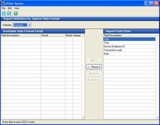
The application provides a default System data format with the following specifications:
System Data Format | Description |
Delimiter | Comma |
Field 1: Date | mm/dd/yyyy |
Field 2: Time | 24 hour: hhmm |
Field 3: Device Employee ID | Up to 30 characters |
Field 4: Transaction Code | Any of the following 2 characters: |
Field 5: Data | If transaction code = 01, 03 or 05, field may be blank. |
Custom Data Format Layouts
If your time record file does not match the default system layout, you may create custom data formats with their own delimiter, fields and field order definitions.
From the Device Records Import screen, click File > Device Setup > File > Setup Data Format.
Create New Data Format
- From the Data Formats screen, click the Add button ( ) on the Tool Bar.
- Specify a name for the data format and any related information for the layout and click the Save button ( ).
- From the Data Formats screen, click File > Create Data Format.
- Specify the delimiter, fields and field order. All fields are required except the data field.
Data Format Definition Screen
2.3. Setup Build Shift Rule
Time records collected via devices are imported into the application for processing. When attendance information is collected, it is stored based on the device Employee ID.
The system performs the following processing steps based on the Build Shift rule configured for that device:
- Pair In and Out time records for an employee to form a complete shift, if possible. The system will look to match In records with the next out record for an employee. If there is an error in the expected In/Out pattern, those time records will be left unpaired.
- Match time records to scheduled shifts according to the mapping information between the device Employee ID and the eTime Xpress Employee ID.
- Apply rounding rules to time records, if configured.
2.3.1. Create Build Shift Rule Name and Description
From the Device Records Import screen, click File > Device Setup > File > Setup Build Shift Rule.
- From the Build Shift Rules screen, click the Add button ( ) on the Tool Bar.
- Specify a name for the build shift rule and any related information for the layout and click the Save button ( ).
A Build Shift Rule is made of several configuration settings including mapping, matching, rounding rules and default information. At a minimum, the items in Build Shift Rule - Setup Employee should be completed.
2.3.2. Setup Build Shift Rule for Employees
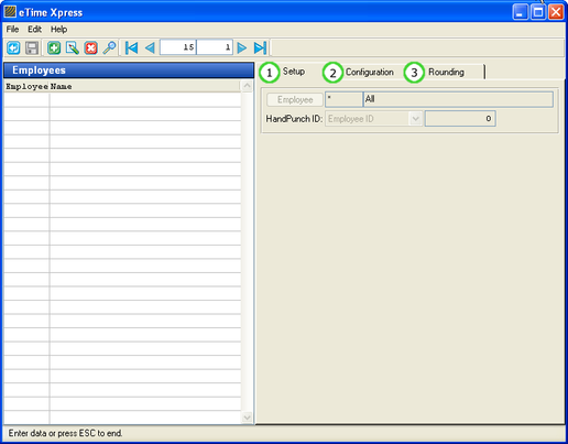
From the Build Shift Rule screen, click File > Setup Employees.
Device Records – Employee Setup with Annotations
Annotation | Description |
(1) Setup Tab | Specify eTime Xpress Employee ID and device ID mapping. |
(2) Configuration Tab | Shift Matching Rules define the time range filter to be applied when matching time records against scheduled shifts. If a time record cannot be matched to a schedule shift, the default customer, site and service will be applied. |
(3) Rounding Tab | Specify rounding rules. |
2.3.2.1. Branch Default Values
When defining Configuration and Rounding rules, they are preset to 'Use Branch Defaults'. Branch Defaults are the general attendance settings applicable to employees within a branch. If the Branch Defaults do not apply to an employee, you may define specific settings by un-checking the applicable 'Use Branch Defaults' check box.
To define or update Branch Defaults:
- From the Device Record - Employee Setup screen, click File > Branch Defaults. The Branch Default Settings dialog box should appear.
- Click the applicable tab in the Branch Default Settings dialog box and define the fields as required.
- Click the OK button to save the new default settings.
2.3.2.2. Mapping Device Employee IDs
Device Employee ID mappings define how to translate Device Employee IDs (i.e. badge number) to eTime Xpress Employee IDs. eTime Xpress allows you to specify either a direct mapping (Device Employee IDs and eTime Xpress Employee IDs are the same) or a custom mapping (Device Employee IDs and eTime Xpress Employee IDs are different).
To define an Employee Device ID mapping:
- From the Employee Setup screen, select an Employee record and click the Add button ( ) on the Tool Bar.
- On the Setup tab, specify the eTime Xpress Employee ID and Device Employee ID mapping rule.
- Click the Save button ( ) to save the Device Employee ID mapping information.
To define a direct mapping for all employees, enter Employee ID = * and Device ID = 0.
Note: Explicit Employee Device ID mappings take priority over any wild card ('*') rules.
2.3.2.3. Shift Matching Rules
Shift Matching Rules define the time range filter to be applied when matching time records against scheduled shifts.
To define shift matching rules:
- From the Employee Setup screen, select an Employee record and click Update button ( ) on the Tool Bar.
- Click the Configuration tab.
- Specify your time range filter for the shift matching rule. For example, if a 1 hour filter before and after a time record is defined, the system will attempt to match employee time records to scheduled shifts for that employee within a 2 hour time range. If eTime Xpress is unable to match attendance information to a scheduled shift, it will attempt to create an unscheduled using the information defined under 'Defaults'.
- Click the Save button ( ) to save the shift matching rules.
2.3.2.4. Rounding Rules
When attendance information is collected, the exact date and time is recorded. Rounding rules allow you to define how attendance information should be rounded.
To define rounding rules:
- From the Employee Setup screen, select an Employee record and click Update button ( ) on the Tool Bar.
- Click the Rounding tab.
- Specify rounding rules based on the available scenarios (scheduled or unscheduled, check-in early, check-in late etc.).
- Click the Save button ( ) to save the rounding rules.
Rounding Rule | Description |
Actual | No adjustment – actual time information will be used. |
Rounded | Round times to the nearest 5, 10, 15 or 30 minutes. |
Scheduled | Overwrite actual times with applicable scheduled shift information. |
2.3.3. Setup Build Shift Rule for Customers/Sites (Optional)
If your time collection device allows for Customer and Site IDs to be recorded, mappings can be defined to translate customer and site information from the device to eTime Xpress Customer and Site IDs. eTime Xpress allows you to specify either a direct mapping (Device IDs and eTime Xpress IDs are the same) or a custom mapping (Device IDs and eTime Xpress IDs are different).
To define a Customer/Site Device ID mapping:
- From the Build Shift Rule screen, click File > Setup Customers/Sites.
- From the Customers/Sites Setup screen, click the applicable Customers or Sites tab and click the Add button ( ) on the Tool Bar.
- Specify the eTime Xpress Customer/Site ID and Device ID mapping.
- Click the Save button ( ) to save the Customer/Site mapping information.
To define a direct mapping for all customers/sites, enter Customer/Site ID = * and Device ID = 0.
Note: Explicit Customer/Site Device ID mappings take priority over any wild card ('*') rules.
2.3.4. Setup Build Shift Rule for Services (Optional)
If your time collection device allows for Service IDs to be recorded, mappings can be defined to translate service information from the device to eTime Xpress service codes. eTime Xpress allows you to specify either a direct mapping (Device IDs and eTime Xpress IDs are the same) or a custom mapping (Device IDs and eTime Xpress IDs are different).
To define a Service ID mapping:
- From the Build Shift Rule screen, click File > Setup Services.
- From the Services Setup screen, click the Add button ( ) on the Tool Bar.
- Specify the eTime Xpress Service Code and Device ID mapping.
- Click the Save button ( ) to save the Service mapping information.
To define a direct mapping for all services, enter Service ID = * and Device ID = 0.
Note: Explicit Service Device ID mappings take priority over any wild card ('*') rules.
3. How to Process Device Time Records
To post time records to shifts in eTime Xpress, please perform the steps outlined in this section.
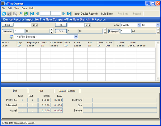
From the Main Menu of eTime Xpress, click Time & Attendance > File > Import > Device Records. The Device Records Import screen should appear as shown in the figure below.
Device Records Import
3.1.1. Import Time Records
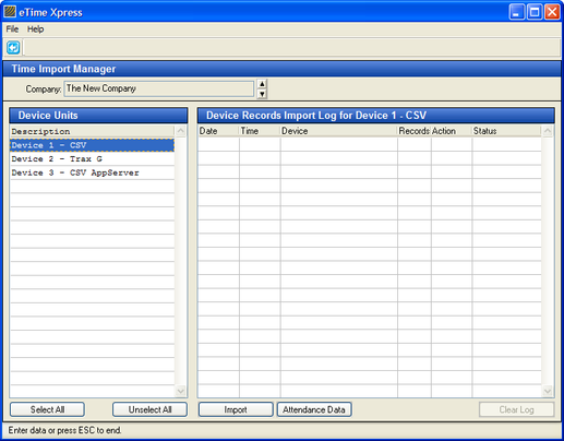
From the Device Record Import screen, click the Import Device Records button from the Tool bar. The Time Import Manager screen should appear as shown in the figure below.
Time Import Manager
To import device time records:
- From the Time Import Manager, select the Company for which you are importing time records.
- Select the Device which you want to download time records and import into eTime Xpress. You can select multiple units using the Select All button or by pressing the [Shift] or [Ctrl] key while selecting units.
- Click the Import button to start the import process. The results of the import should appear in the Device Records Import Log.
Note: If you are importing a large number of time records, it is recommended that you run the import for each device separately to reduce the import file size. Large time record imports will reduce performance and may exceed system buffer limits.
3.1.2. Viewing Imported Time Records
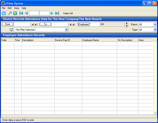
You may review the time records downloaded by clicking the Attendance Data button from the Time Import Manager. The Device Records Attendance Data screen should appear as shown in the figure below.
Device Records Attendance Data screen
View Selectors | Description |
From/To | Specify the date range of the time record. |
Employee | Specify the eTime employee ID of the person. |
Status | All = All time records Posted = Posted time RecordsUnposted = Unposted time records |
Custom Time Record Filter | Select or create a user definable time record filter to search for specific time records. To create your own filters, click button (see the Global Features User Guide for more information). |
Type | All = All time recordsIgnored = Ignored time records |
It is recommended that you regularly generate a view based on the status type 'Unposted' to ensure that there are no unprocessed time records.
3.1.3. Setting Imported Time Records to Ignore
Some devices may automatically delete time records after they have been downloaded leaving eTime as the only source of the time records. As a result, time records cannot be deleted after they are imported into the system. If time records have been incorrectly imported or clock in/out errors exist, you may set those time records to 'Ignore' to exclude those records from being processed.
To set time records to 'Ignore' in the Device Records Attendance Data screen:
- Specify a time range and filter(s) that will display the time records you wish to Ignore.
- Select the time records using the Select All button or by pressing the [Shift] or [Ctrl] key while selecting units.
- Click Data > Set to Ignore.
To undo Ignore follow the steps above but click 'Set to Regular'.
3.2. Post Time Records to Shifts
The post function records in/out information to a shift based on the matched time records and the applicable build shift rule.
3.2.1. Build Shifts – Pairing Time Records and Matching to Shifts
Building shifts is the process of pairing time records and matching them to scheduled shifts based on the build shift rule specified for the device under Device Setup. The build shifts function generates a preview of time record pairing and matching results before they are posted as worked information to shifts in eTime Xpress.
To build shifts:
- From the Device Import screen, load the time records you want to process by specifying the appropriate date range and filters and clicking the Refresh button.
- Click the Build Shifts button in the Tool bar to start the process of pairing and matching time records to scheduled shifts.
If you need to process another group of time records remember to click Refresh followed by Build Shifts.
Note: If time records cannot be matched to a scheduled shift, it will be processed and displayed using the employee's default information (see 'Defaults' section under the configuration tab in the Employee Setup screen).
3.2.2. Reviewing Build Shift Results
Specific groupings of time records can be displayed by updating the available view selection filters.
View Selectors | Description |
From/To | Specify the date range of the time records. |
Hierarchy Filter | Specify hierarchy grouping. |
Status Filter | All: Display All shift records.Posted: Display posted time records.Unposted: Display unposted time records.Scheduled: Display time records matched to scheduled shifts.Unscheduled: Display time records that cannot be matched to scheduled shifts. |
Customer/Site | Specify customer and site combination. Use the spin controls to advance to the previous/next active ID. |
Employee | Specify employee ID. Use the spin controls to advance to the previous/next active ID. |
Custom Time Record Filter | Select or create a user definable time record filter to search for specific time records. To create your own filters, click button (see the Global Features User Guide for more information). |
3.2.3. Updating Shifts Before Posting
Prior to posting shifts, you can update the previewed shift information (i.e. In/Out time, break, Customer, Site or Service) to correct any errors.
To update a shift:
- From the Device Import screen, select a shift record from the browser.
- Click the Post tab.
- Click the Update button in the Post tab.
- Update the In/Out time, break, shift tag, Customer, Site or Service information as required. Fields that have been updated from the initial build shift values will be displayed in red.
- Click the Save button in the Post tab to save your changes.
It is important that you post any updates before clicking Refresh - any unposted updates will be lost after each Refresh.
Note: If you have not properly defined the 'Defaults' section under the configuration tab in the Employee Setup screen, you will need to update the Customer, Site and Service information prior to posting the unscheduled shift.
3.2.4. Reallocating Time Records to Different Shifts
Time records are allocated to shifts based on the build shift rules. The Device Records tab displays the time records associated with a shift record. If required, you may manually reallocate time records from one shift to another.
To reallocate time records:
- From the Device Import screen, select the shift record from the browser with the time record(s) you want to reallocate.
- Click the Device Records tab.
- Right-click on the time record you want to move and select Cut.
- Select the shift record from the browser to which you want to paste the time record.
- Click the Device Records tab.
- Right-click on the browser in the Device Records tab and select Paste. The time record should now be moved.
- Right-click on the browser in the Device Records tab and select Recalculate to rebuild the shift.
3.2.5. Setting Time Records to Ignore
Time records are allocated to shifts based on the build shift rules. The Device Records tab displays the time records associated with a shift record. There may instances of erroneous time records caused by user error such as double clocking or miscoding transactions (i.e. In that should be Out or Out that should be In) that should not be processed. If erroneous time records exist, you may set those time records to 'Ignore' to exclude those records from being processed.
To Ignore time records:
- From the Device Import screen, select the shift record from the browser with the time record(s) you want to Ignore.
- Click the Device Records tab.
- Right-click on the time record and select 'Set to Ignore'.
To Undo the Ignore status on a time record, go to the Attendance Data screen, select the time and update the process status using the 'Set to Regular' option.
3.2.6. Setting Process Action
By default, paired time records are set to 'Import' while unpaired time records are set to 'Skip'.
To update the process action of a shift:
- From the Device Import screen, select a shift record from the browser.
- Click the Post tab.
- Click the Action button in the Post tab and update the action value to 'Import' or 'Skip'.
Note: You cannot update the action value if the record has already been Posted.
3.2.7. Posting a Shift
To post a shift:
- From the Device Import screen, select an Unposted shift record from the browser.
- Click the Post tab.
- Click the Post button in the Post tab. The record status value should change from Unposted to Posted.
Note: If a record contains errors (i.e. Customer, Site or Service is not defined), the post button remain insensitive until those errors are fixed.
To post a group of shifts:
- In the View Selector of the Device Import screen, specify the applicable filters for the shifts you want to view, click the Refresh button ( ) and then click the Build Shifts button.
- Click the Post All button on the Tool bar. All Unposted shifts with the process status of 'Import' will be Posted.
3.2.8. Unposting a Shift
To unpost a shift:
- From the Device Import screen, select a Posted shift record from the browser.
- Click the Post tab.
- Click the Unpost button in the Post tab. The record status value should change from Posted to Unposted.
To unpost a group of shifts:
- In the View Selector of the Device Import screen, specify the applicable filters for the shifts you want to view and click the Refresh button ( ).
- Click Data > Unpost > All from the Menu bar. All Posted shifts in the browser will be Unposted.
4. Device Configuration and Management
Select the section for the device type applicable to you.
4.1. HandPunch
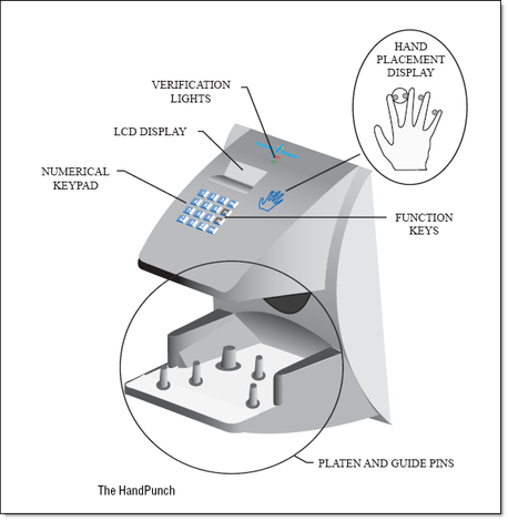
This user manual outlines the minimum steps required to configure a HandPunch unit for use with eTime Xpress. Before continuing with the HandPunch setup, it is recommended that you review your HandPunch user manual.
An illustration of a HandPunch reader is shown in the figure below.
4.1.1. Connecting Power Supply
Connect the power supply provided with your HandPunch Unit.
4.1.2. Connecting Ethernet or Modem
Connect the ethernet or modem cable to your HandPunch Unit (depends on the model and options purchased).
4.1.3. Reset Setup to Factory Defaults
eTime Xpress requires all HandPunch units to be configured with the factory default setup. If your HandPunch unit is loaded with a custom OS configuration, you will need to reset the unit back to the factory default setup as detailed in your HandPunch user manual.
If your HandPunch unit already contains existing employee handprints, select "Setup" when resetting the HandPunch memory.
If your HandPunch unit is new or does not contain existing employee handprints, select "All" when resetting the HandPunch memory.
4.1.4. Understanding How to Program HandPunch Units
Refer to your HandPunch user manual to review the programming procedures associated with your HandPunch unit – pay special attention to the sections labeled: Authority, Sequence and Navigating the HandPunch Menus.
4.1.5. Setup HandPunch Site Parameters
Refer to your HandPunch user manual to setup the following HandPunch settings:
Setting | Description |
Language | Select language preference. |
Date Format | Select mm/dd/yy to correspond to the default date format of eTime Xpress. If you have updated your eTime Xpress date format, please select the matching format. |
Date and Time | Set date and time. |
Set Address | Set as default ('0'). |
Set ID Length | Set as default ('6') and then set T&A mode to 'Yes'. |
Set Serial | If connecting via Ethernet, enter IP address, Gateway and Host Bit.If connecting via Modem, enter 'Y' for RS-422 and specify a baud rate of 9600. |
Set Output Mode | Not applicable. |
4.1.6. Recording Hand Prints
Refer to your HandPunch user manual to add employee and supervisor access to the HandPunch unit. When first configuring a HandPunch unit, you should first create a supervisor to act as an administrator for the unit.
4.1.7. Recording Time Records with HandPunch Units
After your employees have been registered for HandPunch access, you may start using the HandPunch units to record time.
To record time, the employee is required to perform the following:
- Enter their HandPunch ID and press the 'Enter' button. The HandPunch unit should be in standby mode and display "Enter ID". If an invalid ID is entered, an audible double-beep will sound.
- Select the attendance action.
Option | Description |
(1) IN | Check-In to shift (start of shift). |
(2) OUT | Check-Out of shift. |
(3) BACK | Returning to shift. The BACK option should be used when returning to an existing shift. If the IN option is used when returning to an existing shift, it will be recorded as the start of a new shift. |
If (3) BACK is selected, a further selection menu will appear:
Option | Description |
(1) LUNCH | Back from lunch. |
(2) BREAK | Back from break. |
(3) CALL BACK | Was called back to work |
- Verify identity. The Handpunch unit will display "PLACE HAND" – the employee should place their hand in the platen and guide pins (see Handpunch user manual section 'Proper Hand Placement'). A single-beep indicates a pass ('Okay') and a double-beep indicates a fail ('Try Again').
When an employee pass is verified, the following message will appear:
OKAY (USER ID)
SCORE IS: (SCORE NUMBER)
The score number on the display reflects how accurately the user's hand is placed on the platen. Scores that vary greatly between low and high numbers are indicative of inconsistent hand placement. Scores above 50 are indicative of improper hand placement or of a drastic change in the physical appearance of the hand. When this occurs, emphasize to the employee the importance of sliding the hand onto the platen and keeping the hand flat. Please refer the HandPunch user manual section under Read Score for more information.
4.1.8. Register HandPunch dll
All PCs connecting remotely to HandPunch units via eTime Xpress (i.e. to synchronize handprints, download attendance data etc.) must register the HandPunch dll in the system directory of the PC.
To register the HandPunch dll on a PC:
- Download the HandPunch dll from the Celayix Customer Area.
- Unzip the file and open the rsidll32 folder.
- Copy the 'rsidll32.dll' file and paste it to the 'system32' directory found in the PC's systemroot path (i.e. c:\windows\system32). The systemroot path can be found by running the 'set systemroot' command from the PC's Command Prompt.
4.1.9. HandPunch User Manual References
The table below lists the required steps to setup your HandPunch unit along with references to the applicable user manual. Please refer the HandPunch model applicable to you.
HandPunch 2000 Setup | Applicable User Manual Section |
Connecting Power Supply | Wiring pg. 10Wiring Connections pg. 17 |
Connecting Modem | Modem Host Computer Connection pg. 11Wiring Connections pg. 17 |
Reset Setup to Factory Defaults | Erasing the Memory pg. 21 |
Programming HandPunch | Enter Command Menu pg. 25-27Programming the HandPunch pg. 29-32 |
Setup HandPunch Site Parameters | Setup Menu pg. 34-38 |
Setting Time & Attendance Mode | Set ID Length pg. 36 |
Configuring IP Address | n/a |
Recording Hand Prints | Enrollment Menu pg. 39-43 |
HandPunch 3000/4000 Setup | Applicable User Manual Section |
Connecting Power Supply | Wiring pg. 12Wiring Connections pg. 31 |
Connecting Ethernet or Modem | Ethernet Host Computer Connection pg. 19Modem Host Computer Connection pg. 19Wiring Connections pg. 31 |
Reset Setup to Factory Defaults | Erasing the Memory pg. 43 |
Programming HandPunch | Enter Command Menu pg. 47-49Programming the HandPunch pg. 51-54 |
Setup HandPunch Site Parameters | Setup Menu pg. 56-62 |
Setting Time & Attendance Mode | Set ID Length pg. 59 |
Configuring IP Address | Set ID Length pg. 59 |
Recording Hand Prints | Enrollment Menu pg. 63-68 |
Note: When referring to a HandPunch user manual, please search based on the specific section heading provided. The page references may change if the HandPunch user manuals are updated by Recognition Systems.
4.1.10. Manage Biometric Templates
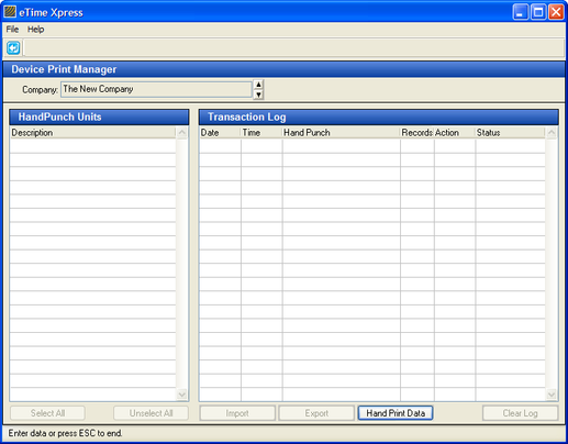
eTime Xpress allows you manage the synchronization of hand prints between various units by importing them into eTime Xpress. The consolidated list of hand prints can then be exported to multiple units - this eliminates the need to physically enroll employees at each HandPunch unit. Many organizations designate a master HandPunch unit to centrally record employee hand prints. Hand prints can be imported to the master HandPunch unit and then exported to other HandPunch units.
From the Device Setup screen, click File > Import/Export Device Prints. The Device Print Manager screen should appear as shown in the figure below.
Device Print Manager for Importing/Exporting Hand Prints
4.1.10.1. Import Hand Prints
- Select the HandPunch units which you want to import hand prints. You can select HandPunch units using the Select All button or by pressing the [Shift] or [Ctrl] key while selecting units.
- Click the Import button.
- Select Overwrite (imports new hand prints and overwrites any duplicate hand prints) or Append (imports new hand prints and skips any duplicate hand prints) hand prints during the import process. The results of the import should appear in the Transaction Log.
You may review the hand prints imported by clicking the Hand Print Data button. The HandPunch Hand Print data screen displays all of the handprints imported into eTime Xpress. You may view the hand prints based on the date imported and delete hand prints if required.
4.1.10.2. Export Hand Prints
- Select the HandPunch units which you want to export hand prints. You can select HandPunch units using the Select All button or by pressing the [Shift] or [Ctrl] key while selecting units. You can view a list of hand prints to be exported by clicking the Hand Print Data button.
- Click the Export button.
Select Overwrite (delete all existing handprints from the HandPunch and reload new list of hand prints) or Append (loads new handprints and skips duplicate).
4.1.11. Entering Shift Details (Optional)
When recording attendance, employees can be prompted to enter additional shift details or job information after pressing the F1 key on the HandPunch 4000.
Note: Using the F1 key replaces the normal HandPunch login process.
Required Steps:
1. Disable Time & Attendance Mode
For each HandPunch unit requiring entry of shift details, ensure that T&A mode is set to 'No' (see Setup HandPunch Site Parameters in this guide).
2. Load Function Key Menu
To enter shift details, you are required to upload a customized function key menu to each applicable HandPunch unit.
To load a custom function key menu to a HandPunch unit:
- Download and save the applicable function key menu from the Celayix Customer download area as instructed by Celayix Support.
- From the Device Import screen, select File > Setup Devices.
- Select the HandPunch unit to which you want to upload the function key menu.
- From the Device Setup screen, select File > Load Function Key Menu.
- Specify the location of the function key menu that you want to load to the selected HandPunch unit. Repeat for each applicable HandPunch unit.
4.2. TraxG/EtherTrax/FingerTrax
Before continuing with the TraxG setup, it is recommended that you review your TraxG device manuals provided. TraxG device manuals are available for download in the Celayix customer area.
Device Manual (PDF) | Description |
929 TRAX+G Manual-ENG-28 | Technical manual |
929 FingerTRAX+G SU Addendum-ENG-17 | Administration manual |
An illustration of a TraxG device interface is shown in the figure below.
4.2.1. TraxG Terminal Setup and Enrollment
The following references the main configuration and maintenance items for TraxG terminals by the applicable device manual and section.
Installation | Device Manual (PDF) | Section |
Fixing the terminal in place | Technical manual | 2.1 |
Connecting via Ethernet | Technical manual | 2.4.10 |
Reset Button | Technical manual | 2.8 |
Maintenance | Administration manual | 6, 6.1, 6.2 |
Device Settings | Manual | Section |
Using the Terminal | Technical manual | 3.1 to 3.2.2 |
Setting the Time and Date | Technical manual | 3.3.1 |
Ethernet configuration (see Local Address and Subnet Mask) | Technical manual | 3.3.6 |
Set Language | Technical manual | 7.4.1 |
Remote Management | Technical manual | 4.1, 4.4 |
Remote control via PC | Administration manual | 3 |
Device Administration | Manual | Section |
Finger Reader Administration Menu | Administration manual | 2 |
Add Finger (enrollment) | Administration manual | 2.1, 6.3 |
4.2.2. Enrolling Users
See Administration manual sections 2.1 and 6.3.
For terminals equipped with barcode, magnetic or proximity readers, swipe the badge when prompted for the user code during enrollment. This action will read the user code from the badge.
4.2.3. Clocking In/Out
To record a clock transaction:
- Select the clock action you are performing by selecting the A, B or D button. If the unit is already displaying the correct clock action it is not necessary to reselect.
- Enter your user code manually or by swiping your badge card.
- Confirm the transaction by validating your finger print, if prompted.
4.2.4. Register Trax dll
All PCs or appservers connecting remotely to TraxG units via eTime Xpress must register the Trax dll in the system directory.
To register the Trax dll on a PC:
- Download the TraxG dlls from the Celayix Customer Area.
- Unzip the file and open the zip folder.
- Copy the 'Proxc.dll' file and paste it to the 'system32' directory found in the PC or server systemroot path (i.e. c:\windows\system32). The systemroot path can be found by running the 'set systemroot' command from the command prompt.
4.2.5. Remote Terminal Management via PC Using TraxPort
Terminals can be managed via network communication over ethernet using the TraxPort application supplied by the device manufacturer. The Traxport application can be downloaded from the Celayix customer area or using the download link provided to you by Celayix support.
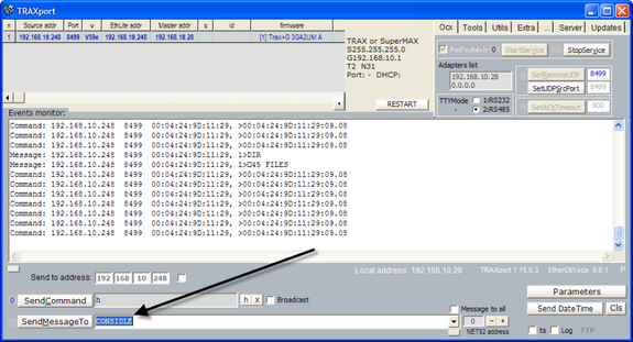
After launching the TraxPort application, the screen should appear as below:
Annotation | Description |
(1) TraxG Terminal List | TraxPort will automatically scan for TraxG terminals connected on the network. The TraxPort application must be run from a workstation that is on the same network as the terminal that you are remotely managing. |
(2) Tools Tab | Allows users to edit, send, receive and delete procedure and device files as well as load firmware. Please contact Celayix support for the appropriate firmware files to be loaded on your device. |
(3) Utilities Tab | Use Trax Remote option to run an emulator that allows you to key in commands just as if you where physically located at the terminal. |
(4) Event Monitor | Lists the commands sent and messages returned from the terminal. |
(5) SendMessageTo | Send commands to the terminal using structured language (see device manuals). |
(6) Parameters | List and update the parameter values set on the device. |
(7) Send Date Time | Send workstation date time values to the device. |
4.2.5.1. Connecting to Terminal
From the TraxPort application, double click on the applicable device listed by the assigned IP address from the TraxG Terminal list.
If no devices are listed, click the StartService button on the OCX tab followed by the RESTART button.
4.2.5.2. Common SendMessage Commands
The following are common commands that can be sent using the SendMessageTo feature in TraxPort.
Command | Description |
%% | Restart terminal |
%%1 | Reset Parameters to factory default |
%%2 | Format terminal |
CONSIDLE | Sets the terminal to Idle. The terminal will display a busy message. |
OFFLINE | Sets the terminal to time and attendance mode. This command is typically used after a terminal has been set to Idle using the 'CONSIDLE' command. |
EXP [# ##] F | Export fingerprint templates to a FINGER file for synchronization and backup purposes. [# ##] is a range of user short codes you want to export fingerprint templates. |
RST [OP Password] | Deletes fingerprint templates on the terminal. OP Password is the operator password set for the terminal. |
IMP F10 | Imports fingerprint templates from the FINGER file on the terminal to the main terminal memory. |
Note: Commands are case sensitive.
4.2.5.3. Loading Firmware and Procedure Files
Your TraxG device should already have the correct firmware and procedure files loaded on the terminal. If the unit has been formatted or reset to factory defaults, please contact Celayix support for assistance.
To upload firmware:
- From the TraxPort application, select the terminal.
- Click the Tools tab > LoadFW.
- Browse to folder containing the firmware files provided by Celayix support and select.
- Click LoadFW again.
To upload procedure files:
- From the TraxPort application, select the terminal.
- Click the Utils tab > Job.
- Browse to folder containing the procedure files provided by Celayix and select one file. It is necessary to select only a single file contained the folder – TraxPort will automatically load all procedure files in the folder.
- Click Job again.
4.2.5.4. Synchronizing User Codes and Finger Print Templates
If an employee can record attendance transactions from multiple terminals, it will be necessary to register their user code and finger print template at each terminal. The synchronization of users' enrollment information across multiple terminals may be managed via TraxPort. Many organizations designate a master terminal to centrally enroll users. User information may then be downloaded from the master terminal and imported to other terminals.
Both the user code file containing the registered employee numbers and the associated fingerprint templates can be synchronized. If your unit does not have a biometric finger reader then only the user code file needs to be synchronized.
Note: Synchronization should be performed when the terminals are not in use. You may use the CONSIDLE and OFFLINE commands using the SendMessageTo feature in TraxPort to temporarily disable user time and attendance functions.
Synchronizing User Codes Download Steps:
- From the TraxPort application, select the terminal containing the master user code file.
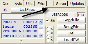
- Click the Tools tab > ListFiles.
- Select the 'USERCODS' file, click RecvFile and save the file on your PC.
Upload Steps:
- Select the target terminal that you want to upload the user code file.
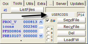
- Click the Tools tab and enter USERCODS P14 (see below)
- Click the file display area on the Tools tab.
- A file selection window should appear. Select the master user code file and click SendFile.
- Repeat for each terminal.
Synchronize Biometric Codes (terminals with finger readers only)
Download Steps:
- From the TraxPort application, select the terminal containing the master fingerprint templates. This should be the same terminal where you downloaded the master user codes file.
- Set the terminal to idle to temporarily disable time and attendance functions on the terminal. Send the 'CONSIDLE' command using the SendMessageTo feature.
- Click the Tools tab > ListFiles.
- Select the 'FINGER' file and click Del. If a 'FINGER' file already exists on the terminal, the export will append and not overwrite existing fingerprint templates in the file.
- Export the biometric finger information for a range of user short codes. Send the 'EXP [# ##] F' command using the SendMessageTo feature where [# ##] is a range of user short codes. For example, entering 'EXP 1 9999 F' will export the fingerprint templates for user short codes 1 to 9999.
The export may take several minutes depending on the number of records being exported. When the export is complete a message '#&FF0' will appear in the Event Monitor.
- Click the Tools tab > ListFiles.
- Select the newly created 'FINGER' file export, click RecvFile and save the file on your PC.
- Set the master terminal back to time and attendance mode. Send the 'OFFLINE' command using the SendMessageTo feature.
Upload Steps:
- Select the target terminal that you want to upload the biometric Finger file.
- Set the terminal to idle to temporarily disable time and attendance functions on the terminal. Send the 'CONSIDLE' command using the SendMessageTo feature.
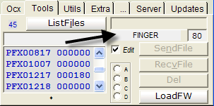
- Click the Tools tab and enter FINGER 80 (see below)
- Click the file display area on the Tools tab.
A file selection window should appear. Select the master Finger file and click SendFile.
- Erase the fingerprint templates on the target terminal. Send the 'RST [OP Password]' command using the SendMessageTo feature where [OP Password] is the operator password for terminal.
- Import fingerprint templates from Finger file to the main memory module on the terminal. Send the 'IMP F10' command using the SendMessageTo feature.
The import may take several minutes depending on the number of records being imported. When the import is complete a message '#&FF0' will appear in the Event Monitor.
- Set the terminal back to time and attendance mode. Send the 'OFFLINE' command using the SendMessageTo feature.
- Repeat for each terminal.
4.2.5.5. Turning Off Finger Validation
The requirement to validate a user's biometric fingerprint template may be disabled on TraxG units equipped with biometric finger readers. When the finger validation is turned off, the user(s) will not be required to submit their finger after their user has entered or scanned their user code.
By User
The user code file can be updated on the device for those employees not required to perform a finger validation when performing a clock transaction.
To disable finger validation by user:
- From the TraxPort application, select the terminal.
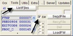
- Click the Tools tab > ListFiles and ensure the edit option is checked-on.
- Double click on the 'USERCODS' file. The contents of the user code file should appear.
Update the value in 21st byte in the user code record to '1' or '2'.
Byte 21 Value
Description
0
Require finger validation
1
Always exempted from finger validation
2
Exempt from finger validation only when using a badge (i.e. if the user code is manually entered, a finger validation is required)
See full explanation of the composition of a user code record in section 4.2 of the TraxG technical manual.- Click the save button.
By Terminal
To exclude finger validations on all clock transactions on a terminal:
- From the TraxPort application, select the terminal.
- Send the 'CFG 55 32' command using the SendMessageTo feature. This will update the 5th byte on parameter 55 to '1' which controls the no finger validation feature.
To re-enable finger validation on the terminal, send the 'CFG 55 0' command using the SendMessageTo feature.
Note: The disable finger validation by terminal option is not supported for TraxG/FingerTrax terminals equipped with Mifare RFID readers.
4.2.5.6. Offline Import of Time Records to eTime Xpress
When a terminal operated offline or on a network that is not accessible from eTime Xpress, the time record file can be downloaded from the terminal using TraxPort. The time record file can then been moved to a location where it may be uploaded to the eTime application.
To perform an offline import of time records:
- From the TraxPort application, select the terminal containing the time records.
- Click the Tools tab > ListFiles.
- Select the 'RECORDED' file, click RecvFile and save the file on your PC.
- Transfer the RECORDED file to a folder that is accessible to the eTime application.
- Open eTime Xpress.
- From the main menu, click Time and Attendance > File > Import > Device Records > Import Device Records.
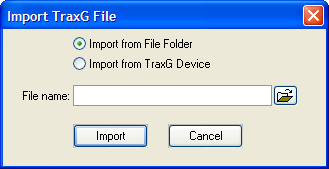
- From the Import Device Records screen, select a device registered as a TraxG device and click File > Import TraxG File.
Specify the file path where the RECORDED file is saved and click Import.
4.2.5.7. Configuring WiFi on EtherTrax Devices
See Technical manual section 3.3.6 Ethernet configuration.
If you EtherTrax unit (non-biometric clock) came with the optional WiFi module, you will need to configure the clock to connect to your wireless access point. When a WiFi module is detected, you will be presented with 5 additional setup options under the IP Config in the Interactive Management Menu on the device. After selecting IP Config, select '1' for Yes when prompted to configure external EtherLite.
WiFi Option | Description |
SSID | Enter the Wireless Network name. The SSID must match exactly (i.e. case sensitive). When entering SSID you may put the unit in upper case or lower case using the up and down buttons on the EtherTrax unit respectively. |
Channel | Your wireless access point must be fixed to a specific channel (i.e. auto channel scan should be disabled). That channel value must be entered in the EtherTrax unit. |
WiFi Quality | Display value only. No configuration required. |
WEP | This value determines the number of bytes to be authenticated in your WEP key. For example, enter 64 if you are using a 10 character hexadecimal code (5 bytes). Enter 128 if you are using a 26 character hexadecimal code (13 bytes). |
WEP Key | Enter your hexadecimal WEP key. Your wireless access point key type is required to be set as hexadecimal. The WiFi module does not support ASCII WEP keys. |
Operating Considerations:
- When the WiFi enabled device has successfully connected to your wireless access point, the LED indicator on the WiFi module will stop flashing;
- To reset and reconnect the device's WiFi connection to your wireless access point, unplug and re-plug the device;
- WiFi operates only when with a dedicated power source and does not operate when the device is operating under battery power.
4.3. XPocket Reader
Before continuing with the XPocket setup, it is recommended that you review your XPocket manual provided. XPocket device manuals are available for download in the Celayix customer area.
Note: The bluetooth feature is supported only on a limited number of Nokia mobile phones (i.e. model 3120).
4.3.1. XPocket Setup
The following are the minimum setup steps required.
4.3.1.1. Install XPocket Software
XPocket devices can be managed via USB using software supplied by the manufacturer. The XPocket application will be used to connect to your XPocket devices for initial configuration and for downloading the time records to a PC so they can be imported into eTime. The XPocket software can be downloaded from the Celayix customer area or using the download link provided to you by Celayix support.
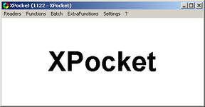
After launching the XPocket.exe, the screen should appear as below:
4.3.1.2. Connecting to XPocket via XPocket Software
To connect to the XPocket device via the XPocket software:
- Launch XPocket.exe software.
- Click Readers > Plant's readers password. Enter the XPocket device password and click confirm. The default XPocket password is '87654321'.
- Click Readers > USB readers list > Search. If the password is correct, status of the device will be listed as Ok. If the password is incorrect, update the password defined in the previous step.
- From the USB Readers List, click Connect.
The default password is '87654321'. This password is required to access the XPocket via the XPocket software.
4.3.1.3. Setting Date and Time
To set the date and time:
- From the XPocket application, click Functions > Send date/time. The XPocket date and time will be synchronized with the date and time of the PC.
4.3.1.4. Updating Device Password
To update the device password:
- After connecting to the XPocket device, click Functions > Configuration parameters.
- Click Get from… button to display the current device parameter values.
- Update the password field - minimum 8 digit numeric password is required. Warning: The device password should be safeguarded. If the password is forgotten, the device will NOT be accessible. The device must be forwarded back to the manufacturer to reset.
- Click Send to… button to update the password on the device.
4.3.2. Using XPocket
XPocket is used to scan compatible RFID cards to collect time records that can be imported into eTime Xpress for time and attendance processing.
The XPocket is pre-loaded with a custom Celayix time collection program that collects time records in a format compatible with eTime Xpress. To run some of the steps outlined in XPocket user manual provided by the manufacturer, you may need to exit the custom Celayix time collection program to return to the manufacturer reader interface.
4.3.2.1. Turning the Reader On
The XPocket reader turns ON automatically, when connected to the USB port of a desktop PC, or it can be turned ON manually, by pressing and holding the center button for one second.
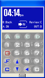
The reader will automatically start the custom Celayix time collection program. The reader should display the following screen:
4.3.2.2. Toggling Between Manufacturer and Celayix Program Interface
To toggle from the custom Celayix time collection interface to the manufacturer interface:
- From the custom Celayix time collection screen press and hold the center Menu button.
- From the Menu screen select the EXIT CYCLE option. Press the left/right buttons to scroll up/down and the center button to select.
- The manufacturer reader interface should be displayed below.
To toggle from the manufacturer interface to the custom Celayix time collection interface:
- From the manufacturer reader interface, press and hold the right and center buttons for 1 second. While still pressing and holding the 2 buttons, release the center button.
- The interface should toggle to the customer Celayix time collection interface below.
4.3.2.3. Turning the Reader Off
The reader may be manually turned off when in the manufacturer interface and pressing and holding the center button for three seconds.
If you are in the customer Celayix time collection interface window, first follow the steps to toggle to the manufacturer interface.
4.3.2.4. Recording a Clock Transaction (In/Out/Back)
To record a clock transaction:
- From the custom Celayix time collection screen, press and hold the right or left SCAN button then scam the RFID card of the employee. The last 6 digits of the ID card will be used to match time records to employees in eTime Xpress.
- The select direction options should be displayed. Select the type of clock transaction to be recorded. Press the left/right buttons to scroll up/down and the center button to select.
Direction | Description |
IN | Select if employee is starting a new shift. |
BACK | Select if employee is returning to the same shift after clocking out such as returning from a break or a call back at the end of a shift. |
OUT | Select if employee is leaving for an unpaid period of time such as breaks or at the end of a shift. |
4.3.2.5. Celayix Time Collection Functions Menu
From the custom Celayix time collection interface window, press the center Menu button.
Option | Description |
SUSPEND | Temporarily suspends the function of the reader. |
CANCEL LAST OPERATION | Not supported. |
CANCEL LAST CYCLE | Not supported. |
EXIT CYCLE | Exits customer Celayix time collection program and toggles to the manufacturer interface. |
4.3.2.6. Manufacturer Information Menu
From the manufacturer interface, press and hold the left and center button.
The manufacturer menu allows you to review time record, firmware, mode and battery status. Please review the manufacturer user guide for more information.
4.3.2.7. Creating Time Record File for Import to eTime Xpress
The XPocket application supports 2 options for download time records to a file:
The 'Acquire records' option downloads all time records created after the last run.
The 'Retrieve records' option downloads all time records since a specified date.
Acquiring Time Records
To acquire time records to a file:
- Launch the XPocket application.
- Plug the XPocket to the PC via USB.
- Connect to the XPocket.
- From the XPocket application, click ExtraFunctions > Production > Acquire records.
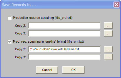
- Check-on the option for 'oneline' format and specify the file name and destination path where you want the time record file saved. Click OK.
- Import the time record file using the Device Record module in eTime Xpress.
- After the time records have been successfully imported into eTime Xpress, erase the memory of reader, if required.
Retrieving Time Records
Note: Due care should be taken when running the retrieve option to not generate time records with overlapping date periods. This will result in duplicate records being imported into eTime Xpress.
To retrieve time records to a file:
- Launch the XPocket application.
- Plug the XPocket to the PC via USB.
- Connect to the XPocket.
- From the XPocket application, click ExtraFunctions > Production > Retrieve records.
- Select the date since for the period you want to retrieve time records and click Retrieve.
- Check-on the option for 'oneline' format and specify the file name and destination path where you want the time record file saved. Click OK.
- Import the time record file using the Device Record module in eTime Xpress.
- After the time records have been successfully imported into eTime Xpress, erase the memory of reader, if required.
4.3.2.8. Erasing Time Records From Memory
Each XPocket comes with 16KB of SRAM. This allows for approximately 2500 eTime clock transactions before the memory needs to be erased.
To erase time records:
- Launch the XPocket application.
- Plug the XPocket to the PC via USB.
- Connect to the XPocket.
- From the XPocket application, click Functions > Erase records.
4.3.3. Resetting Device
Your XPocket should already come preloaded with the firmware and procedure files compatible with the application. If it becomes necessary to reset the unit and reload the setup files, please contact Celayix support to download the required files and follow the steps below in sequence.
4.3.3.1. Load Firmware
To load firmware:
- From the XPocket application, click Functions > Download Firmware.
- Select the firmware file and click Open. DO NOT switch off or manually reset the XPocket device during the update - the XPocket device will restart when the update is complete.
- Click Functions > Send reset + default.
4.3.3.2. Load Strings List
The strings list contains the display descriptions in the menu interface.
To load strings list:
- From the XPocket application, click Functions > Strings list.
- Click Read file, select the stringslist.txt file and click Open.
- Click Send to… button to load strings list.
4.3.3.3. Load Production Program
The production program determines what information will be collected during a clock transaction.
To load production program:
- From the XPocket application, click ExtraFunctions > Production > Program.
- Click Read file, select Replace list, click Execute, select ProductionProgram.txt and click Open.
- Click Send to… button to load production program.
4.3.3.4. Load Production Table
The production table determines the values to be displayed associated with the production program.
To load production table:
- From the XPocket application, click ExtraFunctions > Production > Tables.
- Click Read file, select Replace list, click Execute, select ProductionTable.txt and click Open.
- Click Send to… button to load production table.
4.3.3.5. Load Configuration Parameters
To load configuration parameters:
- From the XPocket application, click Functions > Configuration parameters.
- Click Read file, select the configuration.txt file and click Open.
- Click Send to… button to load configuration parameters.

